7. Key Sustainable Best Management Practices for Sustainable Resilience to Extreme Weather Events and Wildfires
SBMPs are effective and practical methods or techniques to build or adapt a sustainable and climate impact–resilient environmental remediation site. SBMPs are an integral part of SRR. In other guidance, when sustainability and resilience are addressed, they may be referred to as simply BMPs.
SBMPs for resilience to extreme weather events and wildfires are often different from SBMPs for implementing a green cleanup. Green cleanups consider all environmental effects and attempt to minimize the environmental footprint of a cleanup, often with the goal of reducing further contribution toward climate change. This approach is important, and SBMPs for greener cleanups are provided by ITRC (2011a), ASTM (2016), and various federal (for example, the USEPA’s Greener Cleanups website), state (for example, Ecology 2017), and other greener cleanup guidance.
This section identifies important SBMPs, key resources, and additional considerations for evaluating, implementing, and maintaining resilience to extreme weather and wildfire events at a remediation site. Response considerations and actions are also included. SBMPs are organized by type of extreme event, but some SBMPs may be applicable to more than one extreme event. Cited references provide the resources available to investigate SBMPs based on the type of remedy. Figure 7-1 describes the cyclical process to implement SBMPs. Section 6.2.3 has detailed vulnerability assessment information and additional resources. Once the different vulnerabilities of the site are identified, Table 7-1 can be used to identify the relevant SBMPs based on the factors likely to occur or already occurring at the site. Detailed lists of SBMPs are included in the discussion of the extreme event.
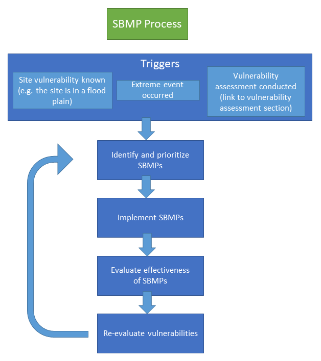
Primary vulnerabilities may cause secondary or cascading vulnerabilities. SBMPs for all associated vulnerabilities should be reviewed at this stage.
If SBMP requires maintenance, make sure it is included in OM&M plan.
Did SBMP address vulnerability as expected?
IF no,
Is SBMP maintenance being conducted?
Does SBMP need optimization?
Is a different solution needed?
If yes,
Consider optimization opportunities
Re-evaluation of vulnerabilities should include more than a re-evaluation of the original trigger-identified vulnerability. This re-evaluation should include a holistic vulnerability assessment (link to vulnerability assessment section) and a review of the prioritization of previously identified vulnerabilities.
The re-evaluation may identify new vulnerabilities due to changing site conditions, project stage, occurrence of an extreme weather event or wildfire, or other additional information.
Figure 7‑1. SBMP process.
The SBMP Identification and Prioritization Tool (SBMP Tool) can be used to create a site-specific summary of SBMPs and document if specific SBMPs are applicable, prioritize SBMPs, and track implementation.
This section does not replace policy or regulatory standards, provide detailed design criteria for individual site-specific use, or verify or certify SBMPs.
Table 7‑1. Relevant SBMPs based on climate change factors.
| Changes in Precipitation | ||||||||||||
| Increase | X | X | X | X | X | X | X | |||||
| Decrease | X | X | X | X | X | X | ||||||
| Changes in Temperature | ||||||||||||
| Increase | X | X | X | X | X | X | ||||||
| Decrease | X | X | ||||||||||
| Changes in Water Level | ||||||||||||
| Increase | X | X | X | X | X | X | X | |||||
| Decrease | X | X | X | X | X | X | ||||||
| Other | ||||||||||||
| Increased storm frequency or intensity | X | X | X | X | X | X | X | X | ||||
SBMPs can be used at any stage of a remediation project, from vulnerability assessment and site investigation to the 30th year of OM&M of a remedy. For example, SBMPs can help identify changes that need to be made to ensure the resilience of existing infrastructure and the remedial design.
If possible, SBMPs are considered at the earliest stages of project development (Section 6.1), such as during preplanning activities, Phase 1 environmental site assessments, and the initial investigation. Incorporating SBMPs at the earliest stages of the Remedial project life cycle provides the greatest opportunity to reduce potential impacts from extreme weather events and wildfires.
7.1 SBMPs Universally Relevant to Extreme Weather Events and Wildfires
SBMPs are aligned with SRR. The following SBMPs are generally applicable to any extreme weather event or wildfire. Event-specific SBMPs can be located under the applicable effects:
| Wind | Fluctuating Groundwater Elevation Levels | Pre-Wildfire | Storm Surge |
| Snow and Hail | Bank and Shoreline Erosion | Post-Wildfire | Sea-Level Rise |
| Flooding | Evapotranspiration | Permafrost Thaw |
7.1.1 Assessing Vulnerability
Assessing whether the site is exposed to extreme weather events or wildfires, and then how vulnerable the site is to those events, is key to building resiliency. See Sections 6.1.3 and 6.1.4.1 for an overview of how to conduct an exposure assessment, and Sections 6.2.3 and 6.2.5.1 for an overview of when and how to conduct a vulnerability assessment.
- If an extreme event has already occurred at the site, assume the site is vulnerable to that extreme event.
- Also assume the site is vulnerable to associated secondary or cascading events (for example, an event that may occur as a result of the first event, such as flash flooding after a wildfire) identified within the SBMPs.
- Review the relevant SBMPs and implement as applicable.
- Conduct a vulnerability assessment to identify any other extreme events the site may be vulnerable to. See Sections 6.1.3 and 6.1.4.1 for an overview of how to conduct an exposure assessment, and Sections 6.2.3 and 6.2.5.1 for an overview of when and how to conduct a vulnerability assessment. Review state and federal resources to identify local vulnerabilities. Review the relevant SBMPs and implement as applicable.
- If known vulnerabilities exist at the site (for example, it is in a floodplain or has permafrost), assume the site is vulnerable to those extreme events.
- Also assume the site is vulnerable to associated secondary or cascading events (for example, an event that may occur as a result of the first event, such as flash flooding after a wildfire) identified within the SBMPs.
- Review the relevant SBMP checklists and implement as applicable.
- Conduct a vulnerability assessment to identify any other extreme events the site may be vulnerable to experiencing. See Sections 6.1.3 and 6.1.4.1 for an overview of how to conduct an exposure assessment, and Sections 6.2.3 and 6.2.5.1 for an overview of when and how to conduct a vulnerability assessment. Review state and federal resources to identify local vulnerabilities. Review the relevant SBMPs and implement as applicable.
- Perform a vulnerability assessment. This can be done at any stage of the project, but earlier is better. See Sections 6.1.3 and 6.1.4.1 for an overview of how to conduct an exposure assessment, and Sections 6.2.3 and 6.2.5.1 for an overview of when and how to conduct a vulnerability assessment. Review state and federal resources to identify local vulnerabilities.
- Include periodic review and reassessment of the site vulnerabilities.
- Adapt SBMPs to match any changing site conditions.
- Use publicly available tools in the vulnerability assessment. Many state and federal resources can be found in the resources map. Others are included in the SBMP sections based on extreme event. Some vulnerability assessment tools that can be used for multiple extreme events, on a national or local scale, include:
- The U.S. Climate Resilience Toolkit
- ARC-X from USEPA’s Climate Change Adaptation Resource Center
- The Climate Explorer from the National Environmental Modeling and Analysis Center
- NOAA’s Climate Prediction Center
- USEPA’s Underground Storage Tank Finder web map application
7.1.2 Planning and Prioritizing Resilience and Sustainability
- At any stage of the project, seek out and review the traditional ecological knowledge (TEK) relevant to the site. USEPA through policy and memorandum (USEPA 2017c) encourages the integration of TEK into the decision-making process, including as it relates to site cleanup activities.
- At any stage of the project, prioritize green infrastructure.
- Gain input from stakeholders on perceived climate risks and communicate how risks will be evaluated during the site investigation.
- Incorporate extreme weather or wildfire impacts at the earliest project phase possible; at a minimum, update the CSM (Section 6.1.1) to include potential impacts. CSM updates can be made throughout the remediation project life cycle.
- Integrate consideration of extreme events in contracting and include incorporating SBMPs into the scope of work.
- Include discussions of extreme weather or wildfire risks and effects in public outreach, notification, and public comment and materials.
- Consider conducting a demographic analysis (Section 5.11) to identify and screen potentially highly impacted communities.
- Extend the time horizon when assessing the life of infrastructure and remedies (USEPA 2009).
- For remedies anticipated to operate for 30 years or longer, adaptation to extreme weather events and wildfires is particularly important over time. The USEPA’s Superfund Climate Resilience: Adaptive Capacity website contains resources to maintain or build adaptive capacity.
- Use drones or closed-circuit video for broad or inaccessible areas and continuous monitoring when practical.
- Prepare a crisis management plan for the extreme weather event or wildfire. It should include:
- an emergency operation center if evacuation is necessary
- an area to house essential staff, supplies, and equipment near the facility to limit exposure to the event
- a “plan B”
- Ensure that key personnel (that is, construction manager, project manager, and all subcontractors) understand the site’s vulnerabilities and site crisis management plan through training and periodic review of the plan.
- Provide extreme weather event or wildfire management and response plans for the site to the impacted community.
- Predict the financial risks associated with climate hazards at the site. Case studies may provide insight on predicting financial risks (Appendix A).
- Evaluate vulnerability to climate-based hazards and potential mitigation measures for each remedial alternative.
7.1.3 Remedy Design and Implementation
- Whenever possible use green infrastructure and natural solutions such as native plantings over impervious, manmade solutions. Green infrastructure and natural solutions are typically more resilient. Native plantings should be native to the existing climate with tolerances for the types of climate events the site is likely to experience in the near future.
- Generate primary or secondary power from on-site renewable resources independent of the utility grid. It is important to note that during extreme climate scenarios, even green infrastructure may not be sufficiently resilient to withstand weather extremes.
- Integrate electronic devices for remote control of equipment during extreme weather or wildfires.
- Integrate sensors linked to electronic control devices to either trigger shutdown of equipment or an alarm to alert workers to shut down equipment.
- Move or locate remedy components away from potential danger zones (USEPA 2013a).
- Stormproof infrastructure by repairing, retrofitting, or relocating facilities and equipment to prevent damage and disruptions during extreme weather or wildfire events. The USEPA’s Climate Change Adaptation Resource Center website contains resources and information pertaining to climate impacts on infrastructure.
- Document SBMPs implemented in completion reports.
7.1.4 Operation, Maintenance, and Monitoring (OM&M)
- Evaluate the performance of the SBMPs in place following an extreme event.
- Include maintenance of the SBMPs in the site OM&M plan and evaluate that the SBMPs are properly maintained.
- Regularly update the vulnerability assessment and adapt SBMP implementation to match any changing site conditions.
- Review the CSM on a defined and regular basis to determine if adaptations to remedy design and construction need to be made.
- Inspect the alarm systems regularly.
- Regularly update the crisis management plan and OM&M plan.
7.1.5 General BMPs
- Locate equipment where accessibility is guaranteed if maintenance is regularly needed or build redundant systems.
- Maintain accurate as-built drawings so lost, damaged, or inaccessible equipment can be located and identified.
- Evaluate the impact of the extreme event or wildfire on site access, drinking water, septic system, and wastewater infrastructure at and around the site.
7.1.6 Crisis Management
-
Perform an integrity inspection of infrastructure, keeping in mind that anything on the ground surface that penetrates the subsurface is a potential conduit of subsurface and groundwater contamination.
- surface—above-grade equipment, aboveground storage tanks, and electrical equipment (for example, electrical panels, transformers, bushings)
- subsurface—wells, subgrade piping and electrical conduit, and underground storage tanks
- Reevaluate site boundaries and potential pathways for contaminant migration. Sites that have achieved remedy completion may need to be reevaluated if extreme events or wildfires have changed the underlying risk assessment.
- Reassess current monitoring and sampling protocols to ensure continued effectiveness.
- Revise safety procedures as necessary to reflect the likelihood or intensity of surrounding conditions.
- Assess alternative utility and transportation options in case default options are not available.
7.2 Wind
SBMPs for high winds include those universally relevant to extreme weather events and wildfires in Section 7.1. The SBMP Tool can be used to create a site-specific summary of SBMPs and document if specific SBMPs are applicable, prioritize SBMPs, and track implementation.
7.2.1 Introduction/Applicability
Areas prone to drought, hurricanes, tornadoes, and other extreme weather events risk damage due to high winds. This section addresses increased wind hazards (either straight-line or cyclonic) associated with the destruction of remediation site buildings and infrastructure and with the potential erosion of land in and around the remediation area.
Potential direct impacts include power interruption, physical damage, and reduced accessibility. Potential indirect impacts may include unintentional release of contaminants on the remediation site or to neighboring sites, accidental fire, explosions, and ecosystem damage. Overall system failures might result in insufficient treatment of contamination due to treatment system compromises or loss, operational downtime, and unexpected and additional project costs for repairing or replacing the remediation system and/or site infrastructure components (USEPA 2013a).
7.2.2 Assessing Vulnerability
The vulnerability of remediation sites to increased wind should be assessed. In addition to reviewing weather records and forecasts, trends can also be evaluated. See Sections 6.1.3 and 6.1.4.1 for an overview of how to conduct an exposure assessment, and Sections 6.2.3 and 6.2.5.1 for an overview of when and how to conduct a vulnerability assessment.
Consult federal, state, or local sources to determine qualitative or quantitative likelihood of wind impacts in a specific area. These are some relevant resources:
- USEPA’s Underground Storage Tank Finder web map application includes functionality to add ArcGIS layers of wind data viewable at the national and local levels.
- The North Carolina Climate Risk Assessment and Resilience Plan identified likely increase of hurricane intensity in the state (NCDEQ 2020).
- The state of Alaska has developed wind predictive models.
- The Minnesota State Hazard plan identified wind storms, tornadoes, and winter storms as high probability hazards (MDPS 2019).
- Severe winter storms and nor’easters are currently the most frequently occurring natural hazards in Massachusetts. The Massachusetts State Hazard Mitigation and Climate Adaptation Plan predicts a likely increased intensity of storms, with all locations vulnerable, particularly coastal areas (high-wind events, nor’easters, and hurricanes) and central counties (tornadoes).
- The New Jersey Scientific Report on Climate Change states that tropical storms in the state have the potential to increase in intensity (NJDEP 2020).
7.2.3 Planning and Prioritizing Resilience and Sustainability
- Consult local authorities and utilities to identify existing adaptation strategies.
- The New Hampshire Department of Environmental Services Drinking Water & Groundwater Bureau has developed a Climate Change Resilience Plan to adapt to climate change, with specific recommendations for resilience of drinking water systems to severe wind storms (McCarthy 2014).
See Section 7.1.1 for an overview of vulnerability assessment.
Sites vulnerable to high winds may also be vulnerable to wildfire (Sections 7.7 and 7.8), storm surge (Section 7.11), bank and shoreline erosion (Section 7.6), or changes in evapotranspiration (Section 7.10). Review of SBMPs for those events is encouraged.
7.2.4 Remedy Design and Implementation
- Install drought-resistant grasses, shrubs, trees, and other deep-rooted plants to provide shading and wind breaks, prevent erosion, and reduce fire risk (USEPA 2013a).
- Maintain wind-resistant and regularly pruned trees on site. Trees that are diseased, weak-wooded, or have poorly formed branching structure could fall during high winds. Studies show that regularly pruned trees survived Gulf Coast hurricanes at a rate of 73% compared to 46% of unpruned trees (Urban Green 2013).
- Stabilize trees using tie-downs to prevent toppling.
- Plant flood-resistant trees to help ensure that the effects of soil saturation or root rot do not increase the occurrence of trees overturning during high winds following a flood event (Urban Green 2013).
- Build soft caps and armor (through techniques such as replenishing sand or vegetation or installing synthetic fabrics) to stabilize and shield surfaces from erosion, storm surges, and tidal influence (USEPA 2013a). These green infrastructure projects reduce capital investment in built infrastructure for stormwater control and management, slowing erosion, improving aquifer recharge, and lowering energy use.
- Install hard caps (such as those made of reinforced concrete or asphalt) to shield surfaces from extreme erosion, storm surges, and tidal influence, and prevent chronic and acute exposures to contaminants (USEPA 2013a).
- Install wind-resistant windows and doors to prevent pressure-related failures that could lead to other types of damage, such as from water (Urban Green 2013).
- Do not use pea gravel or stone as ballast to secure roofing material or temporary membranes on waste piles. These small ballasts may be lifted by high winds and become dangerous projectiles (Urban Green 2013).
- Construct structural reinforcement to protect or anchor permanent and temporary buildings and equipment from high winds. Reinforcement could include hurricane straps to strengthen the physical connection between the roof and walls of a building, shed, or housing unit (Urban Green 2013).
- Install insulated cover systems made of high-density polyethylene (HDPE) or concrete to protect monitoring equipment, control devices, and well heads from high winds and airborne debris (USEPA 2013a).
- Fortify exposed slopes subject to wind erosion by installing anchors and cables to rock or concrete elements placed against the slope. Alternatively, contain a slope by placing netting to hold back rock and debris (USEPA 2013a).
- Install permanent mounts to allow rapid deployment of a cable tie-down system during extreme wind events (USEPA 2013a).
7.2.5 OM&M
- Maintain wind- and flood-resistant trees on site. Ensure that trees are regularly pruned trees. Trees that are diseased, weak-wooded, or have poorly formed branching structure could fall during high winds.
- Maintain soft caps, armor, and hard caps to stabilize and shield surfaces from erosion, storm surges, and tidal influence (USEPA 2013a).
- Do not use pea gravel or stone as ballasts to secure temporary membranes on waste piles.
- Regularly review wind and storm predictions for the site and adapt SBMP implementation to match any changing site conditions.
7.2.6 General BMPs
- Perform regular vegetation maintenance.
- Perform regular site trash and debris removal.
7.2.7 Crisis Management
- Secure rapid deployment cable tie-down systems to permanent mounts when high winds are predicted.
- Inspect cover systems, tie-downs, and other fortifications when high winds are predicted.
7.3 Snow and Hail
SBMPs for increased snow and hail include those universally relevant to extreme weather events and wildfires. The SBMP Tool can be used to create a site-specific summary of SBMPs and document if specific SBMPs are applicable, prioritize SBMPs, and track implementation.
7.3.1 Introduction/Applicability
Increased snow and hail and severe winter storms can impact remediation sites. Potential direct impacts from snow and hail include power interruption, physical damage, water damage, and reduced accessibility. Potential indirect impacts may include overall system failures affecting the treatment system, possibly resulting in insufficient contaminant treatment, operational downtime, and unexpected and additional project costs for repairs (USEPA 2013a).
Ice and snow tend to accumulate on low-slope and flat roofs more readily. Melting snow tends to run more quickly off roofs with slopes greater than 3 inches of slope in 12 inches of horizontal distance (Figure 7-2).
| 5 pounds per square foot | = | 1 inch of water or ice | = | 3 to 5 inches of packed snow | = | 10 to 12 inches of fresh snow |
Figure 7‑2. Approximate weights of ice and snow.
Source: ITRC SRR Team
7.3.2 Assessing Vulnerability
The vulnerability of remediation sites to snow and hail should be assessed. In addition to reviewing weather records and forecasts, trends can also be evaluated. See Sections 6.1.3 and 6.1.4.1 for an overview of how to conduct an exposure assessment, and Sections 6.2.3 and 6.2.5.1 for an overview of when and how to conduct a vulnerability assessment.
- Consult federal, state or local sources to determine qualitative or quantitative likelihood of snow and hail impacts in a specific area. Some relevant resources include:
- USEPA has tracked change in snowfall in the contiguous 48 states from 1930 to 2007, revealing which areas have seen increased versus decreased frozen precipitation (USEPA 2016a).
- USEPA’s Underground Storage Tank Finder web map application includes functionality to add ArcGIS layers of snow and hail data viewable at the national and local levels.
- The Minnesota State Hazard plan identified hail and winter storms as high probability hazards (MDPS 2019).
- The Alaska Center for Climate Assessment and Policy maintains several GIS resources for predicting temperature and precipitation.
- Severe winter storms and nor’easters are currently the most frequently occurring natural hazard in Massachusetts. The Massachusetts State Hazard Mitigation and Climate Adaptation Plan predicts higher precipitation amounts during winter storms. Heavy snowfall and ice storms are a greater vulnerability in high elevations of western and central MA.
Sites vulnerable to increased snow and hail may also be vulnerable to floods (Section 7.5), fluctuating groundwater levels (Section 7.4), or wind (Section 7.2). Review of SBMPs for those events is encouraged.
7.3.3 Planning and Prioritizing Resilience and Sustainability
- Prepare a snow-event response and removal plan based upon the Federal Emergency Management Agency (FEMA) Snow Load Safety Guide (FEMA 2013).
- Plan contingencies because during a severe winter storm, key functional equipment for maintaining remedial performance (even if protected from snow and hail) may be inaccessible for maintenance or upkeep.
- Evaluate the use of backup power for freeze-protection systems (for example, heat trace and heaters) and temperature monitoring telemetry.
- Plan for secondary impacts: rain-on-snow events create faster snow or ice melt and result in increased water discharge (Section 7.5).
- Consult local authorities and utilities to identify existing adaptation strategies.
7.3.4 Remedy Design and Implementation
- Avoid designing low-grade components if possible. If not, mark or flag key components that could be covered by ice or snow.
- Consider potential additional snow load from an extreme snow or hail event as part of roof design to prevent roof collapse. See the American Society of Civil Engineers (ASCE) Minimum Design Loads and Associated Criteria for Buildings and Other Structures Standard 7 (ASCE 2016) or the locally adopted ground snow loads (U.S. Green Building Council 2018).
- Protect against ice dam formation on low-sloped roofs. The Insurance Institute for Business & Home Safety website and the U.S. Green Building Council (2018) provide useful information on this topic.
- Protect from hail all key functional equipment for maintaining remedial performance. Select equipment that is hail impact–resistant or install hail guards or shields designed to resist uplift pressures, as recommended by the Insurance Institute for Business & Home Safety website or as defined by ASCE standard (ASCE 2016).
- Install rain-resistant louvers to prevent wind-driven snow and hail from entering building louvers, ductwork, or mechanical spaces and leading to dampness, mold, or microbial growth (USEPA 2013a).
7.3.5 OM&M
- Inspect low-grade component marking or flags to ensure they remain visible during snow events.
- Regularly review snow and hail predictions for the site and adapt SBMP implementation to match any changing site conditions.
- Periodically review the snow-event response and removal plan and update if necessary.
7.3.6 General BMPs
- For steep-sloped roofs, increase attic insulation, seal ceiling penetrations, and install waterproof membranes on roof decks at the roof edge (U.S. Green Building Council 2018).
7.4 Fluctuating Groundwater Elevation Levels
SBMPs for fluctuating groundwater elevation levels include those universally relevant to extreme weather events and wildfires in Section 7.1. The SBMP Tool can be used to create a site-specific summary of SBMPs and document if specific SBMPs are applicable, prioritize SBMPs, and track implementation.
7.4.1 Introduction/Applicability
Increased precipitation (Sections 7.3 and 7.5) and sea-level rise (Sections 7.9 and 7.11) may lead to increased inputs of water into local groundwater, causing isolated mounding or widespread increases in groundwater elevation levels. Conversely, decreased precipitation and/or increased pumping can lead to widespread decreases in groundwater elevation levels and changes in evapotranspiration (Section 7.10). Changes in groundwater elevation levels and changes to groundwater flow may impact the assumptions upon which the CSM and remedial design are based. Potential impacts to remedies associated with elevated groundwater levels include physical damage (such as flooding vaults and other subsurface structures, floating underground storage tanks), power outages, submerged well screens, salt-water intrusion, and decreased vadose zones. Potential impacts to remedies associated with decreased groundwater elevation levels include decreased groundwater capture, well screens no longer intercepting groundwater, and increased vadose zones. Fluctuating groundwater levels will affect the OM&M of remedial systems at high levels by flooding, damaging their components, and causing shutdowns at either high or low groundwater levels.
7.4.2 Assessing Vulnerability
The vulnerability of remediation sites to fluctuating groundwater elevations should be assessed. In addition to reviewing weather records and forecasts, trends can also be evaluated. See Sections 6.1.3 and 6.1.4.1 for an overview of how to conduct an exposure assessment, and Sections 6.2.3 and 6.2.5.1 for an overview of when and how to conduct a vulnerability assessment.
Fluctuating groundwater level vulnerabilities may be best assessed through tools used to assess other related vulnerabilities. Sites vulnerable to fluctuating groundwater elevations may also be vulnerable to flooding (Section 7.5), sea-level rise (Section 7.9), storm surge (Section 7.11), bank and shoreline erosion (Section 7.6), increased evapotranspiration (Section 7.10), permafrost thaw (Section 7.12), or increased snow and hail (section 7.3). Review of SBMPs for those events is encouraged.
7.4.3 Planning and Prioritizing Resilience and Sustainability
- Evaluate the existing CSM or develop a new CSM to identify impacts that may occur due to groundwater elevation changes such as:
- contaminant migration or mobilization
- release or sorption of contaminants
- change in contaminants or concentrations
- extent of salt-water intrusion and its impact on existing infrastructure or systems that contact the groundwater
- the effect of increased pumping on nearby groundwater supply wells under low water table levels or drought conditions
- change in fate and transport
- change in groundwater chemistry and microbial populations
- Evaluate the effects of lowered water levels and decreased hydraulic conductivity associated with salt-water and brackish water infiltration farther inland than normal. Consider the impacts of increase in salt concentrations on existing infrastructure or systems that contact the groundwater.
- Consult local authorities and utilities to identify existing adaptation strategies.
7.4.4 Remedy Design and Implementation
-
Design monitoring and treatment systems considering potential changes due to extreme fluctuations in groundwater flow, including direction, depth, volume, and rate. Changes in these parameters could significantly change the effectiveness of the monitoring or treatment. Examples include the following:
- changes in groundwater capture associated with pump-and-treat systems
- reduced effectiveness of vadose zone treatments (that is, soil vapor extraction, bioventing) due to changes in vadose zone thickness
- reduced effectiveness of in situ treatments such as bioremediation and chemical oxidation due to changes in saturated zone thickness, salt-water intrusion, groundwater chemistry, and/or the microbial population
- impacts to monitoring due to submerged monitoring wells or groundwater table lowering to below the screened interval
- Design subgrade structures to remain out of contact with the increased water table level or fortify the structures to resist inundation due to flooding.
-
Consider changing the size and type of culverts or stormwater conveyance channels to address impacts during high groundwater events.
- Potential excess stormwater overland may not infiltrate into the soils or recharge the local aquifer.
- Groundwater may flow into stormwater infrastructure.
- If groundwater levels are projected to increase, consider using well clusters targeting specific transmissive groundwater horizons or multiport well systems that have narrow screens across multiple transmissive horizons.
- If groundwater levels are projected to decrease, consider installing monitoring wells deeper and increasing the length of the well screen.
- Seal monitoring wells and increase the height of the well casing above ground surface.
7.5 Flooding
SBMPs for flooding include those universally relevant to extreme weather events and wildfires in Section 7.1. The SBMP Tool can be used to create a site-specific summary of SBMPs and document if specific SBMPs are applicable, prioritize SBMPs, and track implementation.
7.5.1 Introduction/Applicability
This section addresses flooding that is not specifically associated with sea-level rise, though some overlap may occur. Readers concerned with flooding at a remediation site associated with sea-level rise should also review Section 7.9.
No matter where a site is located, some risk of flooding exists (www.floodsmart.gov). As climate change continues, storm and rainfall patterns will continue to change, with some areas experiencing more storms and higher precipitation rates. Flooding can damage remedial systems that are not properly constructed or protected. As a result, contaminants may migrate or may not be treated sufficiently, operational downtime may occur and cause delays, and unexpected or additional project costs may be needed for repairs (USEPA 2013a).
Potential direct impacts of flooding include redistributing contaminated media, scouring and removal of protective caps, power interruption, physical damage, water damage, and reduced accessibility. Indirect impacts of flooding may include spills, accidental fire, explosions, and ecosystem damage. Additionally, localized, time-constrained recharge from floodwater infiltration or bank storage following flood events could perturb the groundwater system being remediated, including contaminant redistribution, LNAPL reductions, and redox condition changes.
Increased precipitation can cause otherwise permeable soil to become waterlogged, increasing the likelihood of flooding, landslides, and debris flow. Regional increases in precipitation may cause stormwater systems to become overloaded, decreasing their effectiveness to drain stormwater from the remediation site. Even if the site is not in a floodplain or lowland, lower elevation or poorly drained areas of the site may be subject to localized flooding.
Increasingly intense storms can result in flash flooding where the topography, surface soil, or geology do not allow sufficient infiltration. Although most floods can be managed by floodplains, building restrictions, and improved infiltration measures, extreme flooding can overwhelm the capacity of even large acres of floodplains and wetlands. While resilient to most weather conditions, even green infrastructure may be washed away during extreme events.
Flash flooding has the potential to cause additional impacts. Through temporary inundation and high surface-water velocities, flash flooding can damage remedial systems that are not properly constructed or protected. As a result, contaminants may migrate or may not be treated sufficiently, operational downtime may occur and cause delays, and unexpected or additional project costs may be needed for repairs (USEPA 2013a).
Green infrastructure helps mitigate the consequences of flooding by allowing rainwater to infiltrate where it lands, which benefits the wider ecosystem as the rainwater replenishes groundwater and maintains baseflow toward local rivers and streams. It is important to note that green infrastructure elements may create changes in climate, soil, and habitat at the site. Furthermore, the performance of green infrastructure can often affect the chance or intensity of flooding and landslides.
7.5.2 Assessing Vulnerability
The vulnerability of remediation sites to flooding should be assessed. In addition to reviewing weather records and forecasts, trends can be evaluated. See Sections 6.1.3 and 6.1.4.1 for an overview of how to conduct an exposure assessment, and Sections 6.2.3 and 6.2.5.1 for an overview of when and how to conduct a vulnerability assessment.
In general, sites with the following features are more vulnerable to flooding and flash flooding:
- lowland areas near water bodies (Sections 7.9 and 7.11)
- areas where soil and surfaces are impermeable
- areas where there is a regional increase in precipitation (Section 7.3)
- areas vulnerable to hurricanes
- areas with high groundwater elevation levels (Section 7.4)
In 500-year and 100-year floodplains, even in areas with prolonged drought, storm events are more intense (U.S. Green Building Council 2018) and are occurring more frequently (Melillo, Richmond, and Yohe 2014). Statistically, the traditional 100-year floodplain has been found vulnerable to extreme events.
When a site is in areas other than those described above, site areas with lower elevation or poor drainage may be subject to localized flooding.
Flooding vulnerability assessment SBMPs include:
- Use federal, state, and local GIS and online map and model resources to predict the site flood risks. Some resources include:
- FEMA flood map service center provides information on flood hazards, including flood maps and other flood hazard information for a better understanding of flood risks.
- USEPA’s Underground Storage Tank Finder web map provides information on whether a UST is within an estimated flood inundation area using a flood inundation model that estimates FEMA’s Flood Insurance Rate Maps for the conterminous United States where FEMA has not mapped a 100 year floodplain.
- Some state tools:
- New Jersey’s Flood Mapper allows users to conduct flood exposure analysis while evaluating several parameters, including total water levels, hurricane surge, sea-level rise, and more.
- Vermont’s Flood Ready website includes community reports and map tools.
- New Hampshire’s Aquatic Restoration Mapper is an interagency collaboration that manages stream crossing assessment efforts across the state to meet the goals of aquatic restoration, infrastructure safety, and flood resiliency.
- Conduct an engineering analysis to determine the 500-year floodplain:
- Review the overall strategies and stormwater management techniques in the USEPA’s Flood Resilience Checklist to help assess how well a remediation site is positioned to avoid and/or reduce flood damage and to recover from floods.
- Where GIS resources are not available, consult state or local sources to determine qualitative or quantitative likelihood of flood impacts in a specific area, especially where FEMA maps are not available, or where the data used in generating a FEMA map are outdated. The following are potential resources for more information.
- Local authorities or utilities may know of locations and frequency of street or yard flooding.
- The state of Vermont identified inundation flooding as the second most significant natural hazard in the 2018 Vermont State Hazard Mitigation Plan (VEM 2018).
- The Ohio Department of Transportation Infrastructure Resiliency Plan identified increases in extreme rainfall events and resulting flooding as vulnerabilities throughout the state (RSG 2016).
- The North Carolina Climate Risk Assessment and Resilience Plan (NCDEQ 2020) identified the potential for flooding to likely increase inland and in coastal areas.
- The Minnesota State Hazard plan (MDPS 2019) identified flooding as a high probability hazard.
- The Massachusetts State Hazard Mitigation and Climate Adaptation Plan identified more frequent inland flooding over a greater area, and more frequent and severe coastal flooding as predicted hazards.
- The New Hampshire Climate Change Resilience Plan (McCarthy 2014) identified the state as receiving more precipitation each year, with more falling as rain and less as snow. More of this precipitation has fallen in extreme events, there are fewer days of snow on the ground, and spring occurs earlier with earlier ice-out dates and earlier spring runoff.
- The New Jersey Scientific Report on Climate Change (NJDEP 2020) states that annual precipitation in NJ is expected to increase by 4–11% by 2050, and the size and frequency of floods will concurrently increase.
- The Denali Commission has identified communities at risk from flooding in Alaska, published in the Statewide Threat Assessment (University of Alaska Fairbanks Institute of Northern Engineering 2019).
- Consult available state or local data to determine landslide risk.
- The Massachusetts State Hazard Mitigation and Climate Adaptation Plan found that more frequent and intense storms will result in more frequent soil saturation conditions conducive to landslides, particularly around Mount Greylock and the U.S. Highway 20 corridor near Chester.
Sites vulnerable to flooding may also be vulnerable to wind (Section 7.2), snow and hail (Section 7.3), bank and shoreline erosion (Section 7.6), sea-level rise (Section 7.9), storm surge (Section 7.11), permafrost thaw (Section 7.12), or fluctuating groundwater elevations (Section 7.4). Review of SBMPs for those events is encouraged.
7.5.3 Planning and Prioritizing Resilience and Sustainability
- Consult local authorities and utilities to identify existing adaptation strategies.
- The Ohio Department of Transportation Infrastructure Resiliency Plan (RSG 2016) identifies adaptive measures the department is taking to address more frequent and intense floods.
- The New Jersey Department of Environmental Protection developed a Stormwater Infrastructure Toolkit to provide long-term, sustainable, flood resiliency.
7.5.4 Remedy Design and Implementation
- Integrate flood-control measures during remedial design and construction. The American Society for Civil Engineers (ASCE 2014) has developed guidelines for flood-resistant design and construction.
- If possible, design contaminant treatment or containment to be outside the 100- and 500-year floodplains. If the 500-year floodplain is not delineated, a best practice from the U.S. Green Building Council is to use the 100-year floodplain and add 3 feet to the measurements (U.S. Green Building Council 2018).
7.5.4.1 Key SBMPs – Functional Equipment for Maintaining Remedial Performance
Key functional equipment, even if protected from floodwaters, may not be accessible for maintenance or upkeep during flooding. Key SBMPs are as follows:
- Locate the equipment at a minimum above the reported flood stage elevation plus a safety factor. Alternatively, build redundant systems or plan a backup means of getting to the critical equipment.
- Locate key functional equipment (for example, backup generators, blower fans, granular activated carbon units) above the 500-year floodplain or on platforms elevated above the predicted 500-year flood levels. Electrically powered fire protection equipment should also be located above the 500-year floodplain.
- Limit above-grade installations in the floodplain to those that can be armored, protected, or sealed and, if necessary, repaired or reinstalled at relatively low cost.
- Design buildings, tanks, and piping to withstand contact with rapidly moving, floating debris (for example, trees, appliances, cars).
- Install additional wells and aboveground pumps to extract leachate in remediation systems with leachate collection systems.
- Install insulated cover systems made of HDPE or concrete to protect monitoring equipment, control devices, and well heads from flooding (USEPA 2013a).
- Install permanent mounts that allow rapid deployment of a cable tie-down system during flood events (USEPA 2013a).
- Install supplemental anchoring systems to tanks, drums, or other containers located in flood-prone areas.
- Install electronic systems that provide workers with early flood warnings or alert workers to active flooding and enable them to suspend operations and secure system components automatically or remotely. Include remote cameras and substantial lighting or infrared imaging so that workers can assess conditions during and immediately after an event (USEPA 2013a).
7.5.4.2 Key SBMPs – Stormwater Management
- Design or modify drainage systems to handle modeled extreme precipitation events (USEPA 2013a).
- Install robust on-site stormwater management systems, including features such as vegetated and nonvegetated roofs, and limit impervious areas (Urban Green 2013).
- Consider green infrastructure to retain or divert flood waters, and use earthen and vegetated structures wherever possible (USEPA 2013a).
- Design the site to allow for dry site features (for example, access roads, sidewalks, and ramps) during flood events.
- Replace or install mold- and mildew-resistant insulating materials in buildings, sheds, or housing envelopes (USEPA 2013a).
- Install rain-resistant louvers to prevent wind-driven rain from entering building louvers, ductwork, or mechanical spaces and leading to dampness, mold, or microbial growth (USEPA 2013a).
7.5.4.3 Key SBMPs – Site Management
- Install permanent flood-control mitigation systems for previously developed sites located within the 500-year floodplain (U.S. Green Building Council 2018).
Additional key SBMPs are as follows:
- Use flood-resistant plants when applicable (Urban Green 2013).
- Consider designing pads and foundations that can accommodate temporary flood walls (USEPA 2013a).
- Fortify concrete pads by repairing cracks, replacing pads of insufficient size or with insufficient anchorage, or integrating retaining walls along the pad perimeter (USEPA 2013a).
- Consider additional groundwater level monitoring for site areas vulnerable to flooding (Ecology 2017).
- Replace deteriorated pavement or pavement that has hindered stormwater management with permeable pavement (in the form of porous asphalt, rubberized asphalt, pervious concrete, or brick pavers) to filter pollutants, recharge aquifers, and reduce the amount of stormwater entering the storm drain system (USEPA 2013a). Also, see Chagrin River Watershed Partners website for case studies
7.5.5 OM&M
- Periodically review floodplain determinations from FEMA or other sources.
- Maintain wind- and flood-resistant and regularly pruned trees on site. Trees that are diseased, weak-wooded, or have poorly formed branching structure could fall during high winds.
- Maintain soft caps, armor and hard caps to stabilize and shield surfaces from erosion, storm surges, and tidal influence (USEPA 2013a).
7.5.6 General BMPs
- Avoid building contamination mitigation systems in areas that could be affected by flash floods or landslides.
- Maintain an inventory of raw materials and wastes at the site.
- Install secondary containment systems to capture hazardous liquids in the event of leaks (USEPA 2013a).
- Inspect and clean roof drainage at least twice a year (see the Insurance Institute for Business & Home Safety website).
- Inspect pads on a periodic basis and repair or replace if necessary.
- Perform regular vegetation maintenance.
- Perform regular site trash and debris removal.
7.5.7 Crisis Management
- Observe conditions remotely or at a safe distance.
- Safely inspect systems as conditions warrant and look for possible hazards related to damaged electrical systems, exposure to released contaminated media, increased biological hazards, and changed physical conditions (for example, those caused by inundation, siltation, and erosion).
- Conduct a post-flood inventory of raw materials and wastes and compare to the pre-flood inventory.
- Deploy contaminant release-control devices as early and safely possible (for example, adsorbent booms).
- Evaluate damage to wells, trenches, or galleries and the potential for stormwater to flow into groundwater systems through damaged or unsealed wellheads.
- Inspect underground vaults, spill containment structures, piping chases, and areas with buried pipe for siltation or erosion and possible exposure or damage.
- Inspect berms, dikes, stockpiles, and floodwalls for damage from erosion or scouring.
- Inspect surface caps, subaqueous caps, and other waste-containment structures for damage, weakness, or changes.
- Evaluate groundwater contamination for potential floodwater infiltration or bank storage following flood events.
- Reevaluate the stability of steep slopes.
7.6 Bank and Shoreline Erosion
SBMPs for bank and shoreline erosion include those universally relevant to extreme weather events and wildfires in Section 7.1. The SBMP Tool can be used to create a site-specific summary of SBMPs and document if specific SBMPs are applicable, prioritize SBMPs, and track implementation.
7.6.1 Introduction/Applicability
Flooding, storm surge (Section 7.11), and wave action may lead to bank and shoreline erosion. Many flood-related SBMPs (Section 7.5) are aimed at making a site resilient to bank and shoreline erosion.
Potential direct impacts of bank erosion include damage or loss of remediation infrastructure, reduced site accessibility, and spills or releases into water bodies. Possible indirect impacts may include insufficient treatment of contamination due to treatment system compromise or loss, ecosystem damage, and additional project costs. Bank erosion may impact access roads. Key functional equipment for maintaining remedial performance, even if protected from potential direct impacts of erosion, may not be accessible for maintenance or upkeep.
Nature-based solutions are often the most sustainable and resilient. Living shorelines can provide a habitat, improve water quality, and self-restore after an erosion event (NOAA 2015).
7.6.2 Assessing Vulnerability
The vulnerability of remediation sites to increased bank and shoreline erosion should be assessed. In addition to reviewing weather records and forecasts, trends can also be evaluated. See Sections 6.1.3 and 6.1.4.1 for an overview of how to conduct an exposure assessment, and Sections 6.2.3 and 6.2.5.1 for an overview of when and how to conduct a vulnerability assessment.
- Consult federal, state or local sources to determine qualitative or quantitative likelihood of bank and shoreline erosion impacts in a specific area.
- USEPA’s Underground Storage Tank Finder web map application includes functionality to add ArcGIS layers of bank and coastal erosion data viewable at the national and local levels.
- Vermont identified fluvial erosion as the most significant natural hazard in the 2018 Vermont State Hazard Mitigation Plan (VEM 2018).
- In Alaska, the presence or absence of sea ice is an important contributor to the rate of shoreline erosion. The Alaska Climate Adaptation Science Center maintains several GIS resources for sea ice.
- The Denali Commission has identified communities at risk from erosion and flooding in Alaska, published in the Statewide Threat Assessment (University of Alaska Fairbanks Institute of Northern Engineering 2019).
- The Massachusetts State Hazard Mitigation and Climate Adaptation Plan identified increased coastal erosion as a predicted hazard, particularly in Eastham, Orleans, and Yarmouth.
- Consider modeling surface-water flow velocity and erosional forces along banks for future storm events.
- Consult available state or local data to determine landslide risk.
Sites vulnerable to bank and shoreline erosion may also be vulnerable to flooding (Section 7.5), sea-level rise (Section 7.9), storm surge (Section 7.11), wind (Section 7.2), snow and hail (Section 7.3), fluctuating groundwater levels (Section 7.4), or permafrost thaw (Section 7.12). Review of SBMPs for those events is encouraged.
7.6.3 Planning and Prioritizing Resilience and Sustainability
- Consider there may be changes to permitting requirements for work on banks and shorelines in the event of a flood or other natural disaster.
7.6.4 Remedy Design and Implementation
- Consider developing nature-based solutions into a living shoreline. Options include replenishing sand, planting deep-rooted or native vegetation, and incorporating more natural and locally available materials as a buffer.
- If this is determined not to be feasible or sufficient, consider installing riprap, gabions, or segmental retaining walls to fortify streambank or shoreline slopes. Keep installations in place with netting to hold back rock elements or attach anchors and cables to rock or concrete elements placed against the slope (USEPA 2013a).
- Consider removal actions if the contamination is located in areas vulnerable to bank erosion. If removal is not possible, divert water around vulnerable banks to decrease erosion and release potential.
- Identify the annual bank or shoreline erosion rate for comparison to the design life of any structures. Use this information to identify how far to locate structures from the bank or shoreline.
7.6.5 OM&M
- Monitor available river gage data, such as that provided by the U.S. Army Corps of Engineers, to maximize preparation time so that sufficient actions can be taken and potential erosion can be minimized
- Maintain soft caps, armor, and hard caps to stabilize and shield surfaces from erosion, storm surges, and tidal influence (USEPA 2013a).
- Periodically review the annual bank or shoreline erosion rate.
7.6.6 General BMPs
- Repair cracks in concrete pads, replace pads that are not sufficient in size or anchorage, and integrate retaining walls along the concrete pad perimeter (USEPA 2013a).
- Reinforce structures to protect buildings and equipment from foundation failures due to erosion.
7.7 Pre-Wildfire
SBMPs for increasing resilience of a site to wildfire ahead of a wildfire event include those universally relevant to extreme weather events and wildfires in Section 7.1. The SBMP Tool can be used to create a site-specific summary of SBMPs and document if specific SBMPs are applicable, prioritize SBMPs, and track implementation.
7.7.1 Introduction/Applicability
As climate change continues, wildfires are expected to increase in frequency and size. The average temperature in the United States has risen more than 2ºF over the last 50 years. In much of the Southeast and large parts of the West, the frequency of drought has increased coincident with rising temperatures (USGCRP 2009). Increased average temperature and increased extreme temperatures, as well as decreased precipitation and increased frequency of drought, can increase the risk of wildfires capable of spreading to remediation sites and affecting remedy performance (USEPA 2014). In fact, large wildfires have increased nearly fourfold in the West in recent decades, with greater fire frequency, longer fire durations, and longer wildfire seasons (USGCRP 2009). According to Community Planning Assistance for Wildfire, the U.S. fire season is now 84 days longer than it was in 1970, and of the 10 years with the largest acreage burned since 1983, nine have occurred since 2000 (USEPA 2016a).
Wildfires can create additional vulnerabilities at a site. Wildfires in upland areas above contaminated sites can reduce vegetative cover, increasing surface-water runoff and resulting in catastrophic flooding that spreads contamination or impacts remedies (USEPA 2014).
This section identifies resources and describes design and management practices to integrate resilience into the remediation strategy so that the impacts of wildfires are prevented. This section addresses SBMPs before a wildfire occurs; Section 7.8 contains information about post-wildfire SBMPs at a remediation site.
7.7.2 Assessing Vulnerability
The vulnerability of remediation sites to increased bank and shoreline erosion should be assessed. In addition to reviewing weather records and forecasts, trends can also be evaluated. See Sections 6.1.3 and 6.1.4.1 for an overview of how to conduct an exposure assessment, and Sections 6.2.3 and 6.2.5.1 for an overview of when and how to conduct a vulnerability assessment.
It is important to note that green infrastructure elements are not fireproof. Although they are a recommended SBMP for many other extreme events, wildfire risk at the site should be part of the evaluation process prior to installation.
- Consider that, in general, the following types of remediation sites may be vulnerable to more frequent and intense wildfires:
- sites with infrastructure (for example, abandoned mines, underground storage tanks) or treatment infrastructure (for example, pump-and-treat systems, Baker tanks)
- landfills with planted vegetation for erosion control (Ecology 2017)
- sites located in areas with trees or grass that are subject to drought, near the urban-forest interface, or within forested areas
- Use federal, state, and local tools to quantify the current and projected wildfire risk with available GIS resources. Some tools include:
- the National Interagency Fire Center
- USEPA’s Underground Storage Tank Finder
- State tools include:
- Where GIS resources are not available, consult federal, state, or local sources to determine qualitative or quantitative likelihood of wildfire risk in a specific area. Some resources include:
- The Fire-Adapted Communities self-assessment tool can be used to help identify if a site or community is prepared for wildfire events by answering a series of questions.
- The North Carolina Climate Risk Assessment and Resilience Plan (NCDEQ 2020) identified an increased likelihood of conditions conducive to wildfires throughout the state.
- The Minnesota State Hazard plan (MDPS 2019) identified wildfire as a high probability hazard.
- The Massachusetts State Hazard Mitigation and Climate Adaptation Plan identified Barnstable and Plymouth Counties as most vulnerable.
- Wildfire seasons could lengthen and the frequency of large fires could increase in New Jersey, according to the New Jersey Scientific Report on Climate Change (NJDEP 2020).
Sites vulnerable to increased wildfire risk may also be vulnerable to flooding (Section 7.5), wind (Section 7.2), fluctuating groundwater elevation levels (Section 7.4), bank and shoreline erosion (Section 7.6), evapotranspiration (Section 7.10), or permafrost thaw (Section 7.12). Review of the flooding SBMPs for those events is encouraged.
7.7.3 Planning and Prioritizing Resilience and Sustainability
- Establish a wildfire management and response plan (WADNR 2019).
- Contact the local fire department that would service the remediation site to ensure that first responders are aware of the potential risks of the site during a wildfire response and receive education on local SBMPs for wildfire planning.
- Assess the potential for contamination to spread from wildfire and build controls as needed.
- Review and assess measures that the utility provider for the site is taking to reduce the likelihood of causing wildfires, as suggested by the Arizona Department of Forestry and Fire Management.
- Provide information on wildfire management and response plan to site neighbors.
- Include discussions of wildfire risks and effects in public outreach, notification, and public comment efforts and materials.
7.7.4 Remedy Design and Implementation
- Plant vegetation that is drought- and fire-resistant and can regrow quickly (USEPA 2019b, Ecology 2017).
- Create fire barriers (USEPA 2013a, 2019a, b) around infrastructure, treatment systems, areas of contamination, and subsurface points of entry.
- Protect heat-sensitive components from wildfire by installing manufactured systems (for example, radiant energy shields and raceway fire barriers) or enclosing vulnerable equipment or control devices in a concrete structure (USEPA 2019a, b).
- Add or replace highly flammable materials with fire-, mold-, and mildew-resistant insulation materials (USEPA 2019a, b).
- Use metal or HDPE piping, which is more resistant to burning and breakage (Ecology 2017).
- Build a retaining wall of concrete or steel sheet piles to hold back debris (USEPA 2019b).
- Relocate electricity and communication lines from overhead to underground positions to prevent power outages during and after extreme weather events (USEPA 2019b).
7.7.5 OM&M
- Inspect the alarm systems regularly.
- Inspect the heat guards regularly.
- Maintain fire barriers.
- Conduct controlled fire burns around the site to serve as a buffer (NWCG 2017).
- Regularly review fire hazard predictions for the site and adapt SBMP implementation to match any changing site conditions.
- Periodically review the wildfire management and response plan and update if necessary.
7.7.6 General BMPs
- Inspect the integrity of electrical equipment.
- Perform regular vegetation maintenance.
- Perform regular site trash and debris removal.
7.8 Post-Wildfire
SBMPs for increasing resilience of a site to wildfire after a wildfire event include those universally relevant to extreme weather events and wildfires in Section 7.1. The SBMP Tool can be used to create a site-specific summary of SBMPs and document if specific SBMPs are applicable, prioritize SBMPs, and track implementation.
7.8.1 Introduction/Applicability
This section identifies the SBMPs and resources available to manage a remediation site following a wildfire. Wildfires may damage buildings, equipment, treatment systems, and other infrastructure and increase the chance of landslides, erosion, flooding, and debris flow. Green infrastructure—and the ecosystem services it provides—is typically devastated by wildfires. Loss of fauna, flora, clean water, and habitat is often sudden and catastrophic, and may take many years to recover in a manner that will support a wide diversity of plants and animals. These impacts and the variety of other impacts following a wildfire can be compounding, which highlights the importance of a fast, efficient response. Once the immediate response is complete, review the pre-wildfire SBMPs in Section 7.7 to build resiliency into the remediation site.
7.8.2 Assessing Vulnerability
Understanding the risks (for example, landslide, erosion, and flooding) after a wildfire occurs at a remediation site can help decrease response time and increase efficiency. See Sections 6.1.3 and 6.1.4.1 for an overview of how to conduct an exposure assessment, and Sections 6.2.3 and 6.2.5.1 for an overview of when and how to conduct a vulnerability assessment.
- The following should be considered to assess potentially compounding impacts after a wildfire:
- Identify areas newly exposed due to vegetation loss.
- Review SBMPs for wind (Section 7.2) and flooding (Section 7.5).
- Monitor surface-water and groundwater conditions (Section 7.4). Mobilization of sediments, nutrients, dissolved organic matter, impacts on municipal treatment facilities, etc., can directly impact water quality (Tecle and Neary 2015, Knoss 2018, Bladon et al. 2008).
- Identify areas newly exposed due to vegetation loss.
- The following should be considered to assess the potential impacts of wildfires on contamination:
- Evaluate burn severity. In general, denser site vegetation corresponds with a longer fire and, therefore, a more significant impact to the soil.
- Evaluate the permeability of soils and assess if there are any conductivity changes.
- Monitor surface water to identify if new migration pathways were established and contaminant flow patterns changed from vertical to lateral.
- Reevaluate site boundaries and potential pathways for contaminant migration.
- Identify if key functional equipment for remedial performance was destroyed.
- Determine if on-site hazardous materials previously contained have been dispersed.
- Investigate whether new contaminants were generated from burning of the on-site contaminants.
- Sample to determine if dioxins and furans were generated at levels of concern as a direct result of the fire.
- Assess the long-term vulnerability (Section 7.1.1) of the site to wildfires. The original site characterization and design of cleanups may not reflect increasing wildfire vulnerability (USEPA 2014).
- Reassess risk factors and rankings for risk-based cleanup strategies based on increasing wildfire risk.
Sites vulnerable to increased wildfire risk may also be vulnerable to flooding (Section 7.5), wind (Section 7.2), fluctuating groundwater elevation levels (Section 7.4), bank and shoreline erosion (Section 7.6), evapotranspiration (Section 7.10), or permafrost thaw (Section 7.12).
7.8.3 Planning and Prioritizing Resilience and Sustainability
Although it is important to immediately respond after a wildfire to reduce additional site impacts (Section 7.8.4), it is also important to consider long-term site conditions and develop a plan to reduce the chances of another fire and help reestablish the ecosystem of the site. When rebuilding a site or a treatment system or redesigning the treatment system, SBMPs for wildfire resilience should be integrated in the planning phase.
At a minimum, the first two items below should be performed as part of the long-term post-wildfire response plan at a site:
- Review pre-wildfire SBMPs (Section 7.7).
- Document site-specific lessons learned to ensure that the site and remedial treatment rebuild are resilient.
- Assess if site conditions have changed. For example, land cover that is altered can result in the need to modify stormwater controls, manage invasive species, and rebalance the hydrologic system (Vaillant, Kolden, and Smith 2016).
- Perform an integrity inspection of infrastructure, keeping in mind that anything on the ground surface that penetrates the subsurface is a potential conduit of subsurface and groundwater contamination.
- Surface—above-grade equipment, aboveground storage tanks, and electrical equipment (for example, electrical panels, transformers, bushings)
- Subsurface—wells, subgrade piping and electrical conduit, and underground storage tanks
- Reevaluate site boundaries and potential pathways for contaminant migration. Sites that have achieved remedy completion may need to be reevaluated if wildfires have changed the underlying risk assessment.
- Reassess current monitoring and sampling protocols to ensure continued effectiveness.
- Revise safety procedures as necessary to reflect the likelihood or intensity of surrounding conditions.
- Assess alternative utility and transportation options in case default options are not available.
7.8.4 Remedy Design and Implementation
If the remediation area is susceptible to erosion, landslides, or flooding, the following modifications to the remedy design should be implemented to reduce post-wildfire impacts:
- Install dams and channel treatments (Colorado State Forest Service) to reduce the velocity of water runoff (for example, install straw wattles in a shallow trench to form a continuous barrier and intercept water running down a slope) (USAID 2017).
- Install gabions, bulkheads, retaining walls, and other slope-stabilization treatments (for example, seeding and mulching, Colorado State Forest Service) to help restore soil and reduce impact from rains.
- Install berms, gabions, vegetated swales, and other soil and sediment traps to help reduce soil loss and increase water dispersion (for example, silt fences and log felling, Colorado State Forest Service).
- Till and scarify to help increase infiltration (Colorado State Forest Service).
7.9 Sea-Level Rise
SBMPs for sea-level rise include those universally relevant to extreme weather events and wildfires in Section 7.1. The SBMP Tool can be used to create a site-specific summary of SBMPs and document if specific SBMPs are applicable, prioritize SBMPs, and track implementation.
7.9.1 Introduction/Applicability
Wave action and sea-level rise are associated with increased risk of flooding (Section 7.5) and erosion (Section 7.6). Rising sea levels inundate low-lying lands, erode shorelines, contribute to coastal flooding, and increase the flow of salt water into estuaries and nearby groundwater aquifers. Higher sea levels also make coastal infrastructure more vulnerable to damage from storms due to an increased likelihood of flooding from higher storm surges (USEPA 2016a). An extensive list of tools to help understand and assess site vulnerability to sea-level rise and storm surges, as well as adaptation strategies, are available in the state and federal resource map. Some resources include:
- the coastal flooding section of data.gov
- the USEPA’s Climate Smart Brownfields Manual (USEPA 2016b)
- the contaminated lands section of Adapting to Rising Tides, a program of the San Francisco Bay Conservation and Development Commission
- Sea-Level Rise Adaptation Training at USEPA’s Clu-In.org
- Adaptation Strategies for Resilient Cleanup Remedies from the Washington Department of Ecology (2017)
- New Jersey’s Flood Mapper
Nature-based solutions are often the most sustainable and resilient. Living shorelines can provide a habitat, improve water quality, self-restore, and may even adapt to sea-level rise (NOAA 2015).
7.9.2 Assessing Vulnerability
The vulnerability of remediation sites to sea-level rise should be assessed. In addition to reviewing weather records and forecasts, trends can also be evaluated. See Sections 6.1.3 and 6.1.4.1 for an overview of how to conduct an exposure assessment, and Sections 6.2.3 and 6.2.5.1 for an overview of when and how to conduct a vulnerability assessment.
- Use federal, state, and local tools to quantify the current and projected sea-level rise risk with available GIS resources. Some tools include:
- sea-level change curve calculator from the U.S. Army Corps of Engineers. The middle three trend lines may be the most likely scenarios.
- NOAA sea level rise visualization tool, which shows what sea-level rise will look like at high tide
- NASA Sea-Level Change Portal
- USEPA’s Underground Storage Tank Finder includes functionality to add ArcGIS layers of sea level ride data, viewable at the national and local levels
- state-specific sea-level rise tools:
- Sea-Level Rise and Coastal Flood Web Tools Comparison Matrix was developed by the Nature Conservancy, NOAA Office for Costal Management, and Climate Central.
- The Delaware Department of Natural Resources and Control published a statewide sea-level rise vulnerability assessment with maps and models (DNREC 2012).
- The Hawaii Climate Change Mitigation and Adaptation Commission developed the Hawai’i Sea-Level Rise Vulnerability and Adaptation Report and viewer tool.
- The New Hampshire Department of Environmental Services created the New Hampshire Sea-Level Rise, Storm Surge, and Groundwater Rise Mapper to be a screening tool to plan for future coastal inundation scenarios.
- The New Jersey Flood Mapper allows users to conduct flood exposure analysis while evaluating several parameters, including sea-level rise.
- Washington State maintains an interactive Sea-Level Rise Data Visualization tool.
- The Denali Commission has identified communities at risk from flooding in Alaska, published in the Statewide Threat Assessment (University of Alaska Fairbanks Institute of Northern Engineering 2019).
- Align the projected sea-level rise timeline with the site timeline—for example, if a site will have a 30-year cap, look at sea-level rise predictions at least 30 years out.
- If GIS resources are not available, consult state or local sources to determine qualitative or quantitative likelihood of sea-level rise in a specific area.
- The North Carolina Climate Risk Assessment and Resilience Plan identified with virtual certainty that sea level along the coast will continue to rise (NCDEQ 2020).
- The New Hampshire Climate Change Resilience Plan stated that sea-level rose about 5.3 inches from 1926 to 2001 (McCarthy 2014).
- The New Jersey Scientific Report on Climate Change states that by 2050 there is a 50% chance that sea-level rise will meet or exceed 1.4 feet, and the entire coastal area of NJ will experience more frequent flooding not associated with precipitation. Atlantic City is particularly vulnerable to flooding due to sea-level rise. Overpumped aquifers are vulnerable to salt-water intrusion (NJDEP 2020).
- Georgia Department of Natural Resources reports that the sea level in Georgia’s coastal areas has risen at a rate of 3mm/year for the past 70 years.
- If the site is vulnerable to sea-level rise, quantify the current and projected associated risks, including flooding, storm surge, and shoreline encroachment.
- Use available extreme water-level predictions to understand flooding risk during a storm surge.
- The NOAA Extreme Water Levels tool provides 1% annual exceedance probability levels for specific locations. This value can be added to the predicted sea-level rise value to predict flood water heights during storm surges.
- Use available modeling resources, such as the NOAA Sea-Level Rise Viewer, to evaluate shoreline encroachment in contaminated areas.
Sites vulnerable to sea-level rise may also be vulnerable to flooding (Section 7.5), storm surge (Section 7.11), bank and shoreline erosion (Section 7.6), wind (Section 7.2), fluctuating groundwater elevation levels (Section 7.4), or permafrost thaw (Section 7.12). Review of the SBMPs for those events is encouraged.
7.9.3 Planning and Prioritizing Resilience and Sustainability
- Determine the tolerance for flood risk.
- Contact local and regional planning agencies and infrastructure owners who may service the site, such as the local transportation agency and utilities, to learn if they have any sea-level rise mitigation plans specific to the local area that can be used on site and ensure the site plans are compatible with other regional plans.
- Establish sea-level rise management and mitigation plan (Miller et al. 2019).
- Plan habitat restoration to span a wide range of elevations from subtidal to upland (Ecology 2017).
- Proactively plan and budget for increasingly frequent floods.
- Consider resilient uses for the site, such as park space.
- Monitor water temperature and pH to determine the conditions the remedy should be designed to.
7.9.4 Remedy Design and Implementation
- If possible, design contaminant treatment or containment to be outside the 100- and 500-year floodplains. Statistically, the traditional 100-year floodplain has been found vulnerable to sea-level rise even in areas with prolonged drought. If the 500-year floodplain is not delineated, a best practice from the U.S. Green Building Council is to use the 100-year floodplain and add 3 feet to the measurements (U.S. Green Building Council 2018).
- Consider developing nature-based solutions into a living shoreline. Options include replenishing sand, planting deep-rooted or native vegetation, and incorporating more natural and locally available materials as a buffer to stabilize shorelines. Swamps, marshes, bogs, or other areas vegetated with plants that thrive in saturated soil can reduce the height and speed of floodwaters and provided a buffer from wind or wave action and storm surge (Ecology 2017).
- If this is determined not to be feasible or sufficient, consider installing riprap, gabions, or segmental retaining walls to fortify streambank or shoreline slopes. Keep installations in place with netting to hold back rock elements or attach anchors and cables to rock or concrete elements placed against the slope (USEPA 2013a).
- Monitor groundwater elevations, salinity, pH, sea level, and long-term shoreline impacts such as wave erosion, flooding, or overtopping of seawalls or groundwater barrier walls to design remedial treatment resilient to the impacts of sea-level rise. A drop in groundwater and river flows can lead to decreased hydraulic head, resulting in salt-water and brackish water infiltrating farther inland and potential groundwater quality degradation.
- Consider the increasing prevalence of seasonal and monthly high-tide flooding when planning access to sites and facilities.
- Seal monitoring wells and increase the height of the well casing above the ground surface.
- Build treatment systems at a higher elevation or on platforms elevated above future sea-level projections (Ecology 2017) or build floodable structures.
- Consider that increasing water temperature, increasing acidification, and salinity changes may affect natural attenuation mechanisms, the integrity of the equipment, and the efficacy of the treatment method (Ecology 2017).
- Use materials that are corrosion resistant and compatible with brackish groundwater and surface water for engineered system components.
- Identify the annual bank or shoreline erosion rate for comparison to the design life of any structures. Use this information to identify how far to locate structures from the bank or shoreline.
7.9.5 OM&M
- Periodically review the sea-level rise management and mitigation plan and update if necessary.
- Monitor for the mobilization of contaminants.
- Monitor site conditions to evaluate changes in sea and groundwater temperature, salinity, pH, and elevation.
- Monitor long-term shoreline impacts such as wave erosion, flooding, or overtopping of seawalls or groundwater barrier walls.
- Consider that monitoring may be required indefinitely for alternative remedies that rely on containment and are vulnerable to sea-level rise (Nuttle and Portnoy 1992).
- Maintain soft caps, armor, and hard caps to stabilize and shield surfaces from erosion, storm surges, and tidal influence (USEPA 2013a).
- Periodically review the annual bank or shoreline erosion rate.
- Periodically review floodplain determinations from FEMA or other sources.
7.9.6 General BMPs
- Perform regular vegetation maintenance.
- Perform regular site trash and debris removal.
7.10 Evapotranspiration
SBMPs for evapotranspiration (ET) include those universally relevant to extreme weather events and wildfires in Section 7.1. The SBMP Tool can be used to create a site-specific summary of SBMPs and document if specific SBMPs are applicable, prioritize SBMPs, and track implementation.
7.10.1 Introduction/Applicability
Recent studies conducted by the U.S. Geological Survey (USGS) and NASA’s Earth Observing System Project Science office showed that due to increases in temperature, there has been an increase in the flow between the various stages of the water cycle over most of the United States in the past seven decades. Water has been moving more quickly and intensely through the various stages (Huntington et al. 2018, Kramer et al. 2015). “As the planet warms, we anticipate that the warmer air, which holds more moisture, will lead to more evaporation and precipitation,” said Tom Huntington, a research hydrologist at USGS. If those processes are increasing, it is evidence for an intensifying water cycle” (Patel 2019, page 1).
Furthermore, as temperatures increase, plant transpiration increases, which in turn reduces soil moisture and lowers shallow groundwater elevations. This increase in ET (defined as the sum of evaporation and plant transpiration) poses both short-term and long-term risks for selected remediation projects throughout North America, particularly constructed treatment wetlands, phytoremediation, retention basins, and other surface water–based remediation.
U.S. Department of Agriculture (USDA) Evaporative Stress Index (ESI), USEPA’s Evapotranspiration Calculator Desktop Modeling Tool, and the National Drought Mitigation Center are valuable resources for ET information.
The USDA ESI can be used to identify geographic areas subject to drought.
The USEPA ET Calculator Desktop Modeling Tool can be used to evaluate the site vulnerability to ET and specific risks associated with a given site. This tool estimates ET time series data for hydrologic and water quality models. It was developed specifically for the Hydrologic Simulation Program – Fortran (HSPF) and the Stormwater Management Model, but can be used with other models if they use time series ET data as input.
The National Drought Mitigation Center maintains the U.S. Drought Monitor through a multiagency partnership at the University of Nebraska-Lincoln. It is a map released every Thursday, showing parts of the United States that are in drought. The website includes maps, tabular data, and weekly drought summaries.
7.10.2 Assessing Vulnerability
The vulnerability of remediation sites to increased ET should be assessed. In addition to reviewing weather records and forecasts, trends can also be evaluated. See Sections 6.1.3 and 6.1.4.1 for an overview of how to conduct an exposure assessment, and Sections 6.2.3 and 6.2.5.1 for an overview of when and how to conduct a vulnerability assessment.
- Use federal, state, and local tools to quantify the current and projected ET risk with available GIS resources. Some tools include:
- USDA Evaporative Stress Index
- USEPA ET Calculator Desktop Modeling Tool
- USEPA’s Underground Storage Tank Finder includes functionality to add ArcGIS layers of evapotranspiration data viewable at the national and local levels
- the National Drought Monitor out of the University of Nebraska-Lincoln
- New Jersey Forest Adapt allows users to generate maps with a variety of climate projection data, including temperature and precipitation
- Where GIS resources are not available, consult state or local sources to determine qualitative or quantitative likelihood of ET risk in a specific area.
- The Ohio Department of Transportation Infrastructure Resiliency Plan identified increases in drought and related flash flooding as vulnerabilities throughout the state (RSG 2016).
- The North Carolina Climate Risk Assessment and Resilience Plan identified that severe droughts are likely to be more intense and frequent (NCDEQ 2020).
- The Minnesota State Hazard plan identified drought as a high probability hazard (MDPS 2019).
- The Massachusetts State Hazard Mitigation and Climate Adaptation Plan identified the entire commonwealth as vulnerable to drought, with the frequency and intensity projected to increase during summer and fall.
- The New Jersey Scientific Report on Climate Change states that New Jersey is warming faster than the rest of the Northeast region, with average annual temperatures increasing by 4.1°F to 5.7°F by 2050. Droughts may occur more frequently due changes in precipitation patterns (NJDEP 2020).
Sites vulnerable to increased ET may also be vulnerable to wildfires (Sections 7.7 and 7.8), wind (Section 7.2), or fluctuating groundwater levels (Section 7.4). Review of the flooding SBMPs for those events is encouraged.
7.10.3 Planning and Prioritizing Resilience and Sustainability
- Consult local authorities and utilities to identify existing adaptation strategies.
- The Ohio Department of Transportation Infrastructure Resiliency Plan identifies adaptive measures the department is taking to address more frequent and intense droughts (RSG 2016)
- New Hampshire maintains a Drought Assessment and Response Annex to coordinate the state’s assessment and response activities in the case of a drought emergency (NHDES 2016).
- Monitor surface-water and groundwater elevations for decreasing levels using transducers or other means to plan a design resilient to this impact.
- Monitor for salinity and pH of water systems to plan a design resilient to these impacts.
- Develop protocols to conduct regular checks for plant disease and invasive insect species (for example, fungus, termites, bees, fire ants).
7.10.4 Remedy Design and Implementation
- Install low-level alarm float switches in surface water–based systems (for example, retention ponds, evaporation ponds).
- Select hardy, drought-resistant, local vegetation for covers, phytoremediation projects, and wetlands.
- Install spray-irrigation areas.
- Use dry rot–resistant materials when practical.
7.10.5 OM&M
- Monitor surface-water and groundwater elevations for decreasing levels using transducers or other means.
- Monitor for salinity and pH of water systems.
- Regularly check rubber fittings for dry rot.
- Follow site-specific protocols to regularly check for plant disease and invasive insect species (for example, fungus, termites, bees, fire ants).
- During confluence of extreme conditions (for example, drought, increased temperature, increased ET), conduct regular checks of vegetation for fire potential.
7.10.6 General BMPs
- Perform regular vegetation maintenance.
7.11 Storm Surge
SBMPs for storm surge include those universally relevant to extreme weather events and wildfires in Section 7.1. The SBMP Tool can be used to create a site-specific summary of SBMPs and document if specific SBMPs are applicable, prioritize SBMPs, and track implementation.
7.11.1 Introduction/Applicability
Storm surges occur when high storm winds (Section 7.2) raise the seawater level above the normal anticipated tide. They cause destructive coastal flooding (Section 7.5) and pose a serious risk to people, property, and ecosystems. Depending on the severity of the storm and coastal elevations, storm surges can threaten low-lying, inland areas miles from the shoreline. Rising sea levels (Section 7.9) and greater storm frequency are projected to increase the threat of storm surges in the future.
Storm-surge magnitude depends on many factors, including but not limited to storm intensity, wind speed, and coastal features. The impacts of storm surges are exacerbated by eroded shorelines (Section 7.6), which do not provide an adequate buffer for diffusing wave energy. Over the years, coastal development has reduced natural sediment accretion and beach width, making communities more vulnerable to waves and wind. Storm surges further erode shorelines and limit the buffer potential against future storms (USACE 2007).
In addition to posing an immediate risk to people and property, storm surges damage critical infrastructure, threaten ecosystems, and compromise remediation systems. Transportation infrastructure, wastewater treatment facilities, and drinking water systems may fail. Wetlands and estuary ecosystems are threatened by sediment deposition and salt-water infiltration. Existing remediation systems may be compromised and ongoing remediations disrupted.
Nature-based solutions are often the most sustainable and resilient. Living shorelines can provide a habitat, improve water quality, and self-restore after an erosion event (NOAA 2015).
7.11.2 Assessing Vulnerability
The vulnerability of remediation sites to storm surge should be assessed. In addition to reviewing weather records and forecasts, trends can be evaluated. See Sections 6.1.3 and 6.1.4.1 for an overview of how to conduct an exposure assessment, and Sections 6.2.3 and 6.2.5.1 for an overview of when and how to conduct a vulnerability assessment.
- Use federal, state, and local tools to quantify the current and projected ET risk with available GIS resources. Some tools include:
- the USEPA Storm Surge Inundation Map, an interactive map that illustrates hurricane frequency, storm-surge flooding, and FEMA flood zones
- NOAA’s national storm-surge hazard maps showing coastal areas that are at risk of storm surge, as well as the potential magnitude of the storm surge based on the storm category. In Alaska the presence or absence of sea ice is an important contributor to the impact of storm surges. The Alaska Climate Adaptation Science Center maintains several GIS resources for sea ice.
- USEPA’s Underground Storage Tank Finder web map application includes functionality to add ArcGIS layers of storm surge data viewable at the national and local levels.
- the New Jersey Flood Mapper, which allows users to conduct flood exposure analysis while evaluating several parameters, including storm surge
- Where GIS resources are not available, consult state or local sources to determine qualitative or quantitative likelihood of storm-surge risk in a specific area.
- The North Carolina Climate Risk Assessment and Resilience Plan identified virtual certainty for increased storm-surge flooding in coastal areas (NCDEQ 2020).
- The Denali Commission has identified communities at risk from erosion and flooding in Alaska, published in the Statewide Threat Assessment (University of Alaska Fairbanks Institute of Northern Engineering 2019).
Sites vulnerable to storm surge may also be vulnerable to bank and shoreline erosion (Section 7.6), flooding (Section 7.5), fluctuating groundwater levels (Section 7.4), sea-level rise (Section 7.9), snow and hail (Section 7.3), wind (Section 7.2), or permafrost thaw (Section 7.12). Review of the SBMPs for those events is encouraged.
7.11.3 Planning and Prioritizing Resilience and Sustainability
- Incorporate wetland and estuary protection into infrastructure and remedy planning to provide a buffer against storm surges and coastal erosion (USEPA 2009).
- If possible, design contaminant treatment or containment to be outside the 100- and 500-year floodplains. Statistically, the traditional 100-year floodplain has been found vulnerable to sea-level rise even in areas with prolonged drought. If the 500-year floodplain is not delineated, a best practice from the U.S. Green Building Council is to use the 100-year floodplain and add 3 feet to the measurements (U.S. Green Building Council 2018).
7.11.4 Remedy Design and Implementation
- Consider developing nature-based solutions into a living shoreline. Options include replenishing sand, planting deep-rooted or native vegetation, and incorporating more natural and locally available materials as a buffer to stabilize shorelines. Swamps, marshes, bogs, or other areas vegetated with plants that thrive in saturated soil can reduce the height and speed of floodwaters and provide a buffer from wind or wave action and storm surge (Ecology 2017).
- If this is determined not to be feasible or sufficient, consider installing riprap, gabions, or segmental retaining walls to fortify streambank or shoreline slopes. Keep installations in place with netting to hold back rock elements or attach anchors and cables to rock or concrete elements placed against the slope (USEPA 2013a).
- Preserve coastal lands such as dunes, wetlands, sea grass beds, and oyster reefs as recommended by USEPA’s Green Infrastructure-Coastal Resiliency website.
- Install flood and storm-surge controls and drainage structures to protect critical site and remedy components. Green infrastructure and earthen structures such as seawalls, vegetated berms or swales, detention wetlands, tree trenches, and stormwater ponds, dams, or levees can be used to prevent inundation (USEPA 2013a).
- Identify the annual bank or shoreline erosion rate for comparison to the design life of any structures. Use this information to identify how far to locate structures from the bank or shoreline.
- Move or locate key functional equipment for remedial performance away from potential storm surge or coastal flooding areas (USEPA 2013a).
- Install or relocate overhead communication and electric lines underground to prevent power outages during storms (USEPA 2013a).
- Storm-proof infrastructure by repairing, retrofitting, or relocating facilities and equipment to prevent damage and disruptions during extreme weather events. The USEPA’s Climate Impacts on Water Utilities website (USEPA ARC-X) contains resources and information pertaining to climate impacts on infrastructure.
- Develop off-grid alternate power sources that can supply power during storms. Locate new and backup electrical power above the floodplain (USEPA 2013a).
- Secure storage areas above the 100- and 500-year floodplains. If the 500-year floodplain is not delineated, a best practice from the U.S. Green Building Council is to use the 100-year floodplain and add 3 feet to the measurements (U.S. Green Building Council 2018).
- Use pervious materials instead of impervious surfaces to improve drainage and stormwater flow.
7.11.5 OM&M
- Monitor storm conditions through the National Hurricane Center.
- Regularly review storm-surge predictions for frequency and elevation of surge waters at the site and adapt SBMP implementation to match any changing site conditions.
- Periodically review the annual bank or shoreline erosion rate.
- Maintain soft caps, armor, and hard caps to stabilize and shield surfaces from erosion, storm surges, and tidal influence (USEPA 2013).
- Periodically review floodplain determinations from FEMA or other sources.
7.11.6 General BMPs
- Perform regular vegetation maintenance.
- Perform regular site trash and debris removal.
7.12 Permafrost Thaw
SBMPs for permafrost include those universally relevant to extreme weather events and wildfires in Section 7.1. The SBMP Tool can be used to create a site-specific summary of SBMPs and document if specific SBMPs are applicable, prioritize SBMPs, and track implementation.
7.12.1 Introduction/Applicability
This section is designed to help practitioners identify key SBMPs for designing or adapting remediation sites so that they are resilient to thawing permafrost. Permafrost is defined by the United States Permafrost Association and the U.S. Army Corps of Engineers (USACE) as earth materials that remain continuously at or below 0ºC for at least 2 consecutive years.
Surface activity generally causes some damage to thermal stability in the active layer, causing some degree of permafrost degradation, the main exception being snow compaction in the winter. All tundra types are more sensitive to both chemical and physical damage when the soil is thawed (Cater 2010). Unlike the SBMP guidance for other extreme weather events or wildfires, which address well understood climate phenomena occurring on a more frequent basis or at a higher intensity, large-scale thawing permafrost is a relatively new phenomenon. Arctic air temperatures are rising at approximately twice the rate compared to the rest of the United States (USEPA 2016a, Schnabel, Goering, and Dotson 2020). The Alaska Departmentof Environmental Conservation (ADEC) noted, “Climate change is introducing additional complexity for contaminated site cleanup in the Arctic” (ADEC 2019, page 3).
“The resilience and vulnerability of permafrost to climate change depends on complex interactions among topography, water, soil, vegetation, and snow” (Torre-Jorgenson et al. 2010). At any cleanup site in the tundra, responsible parties should understand the current thermal regime and ground ice types and content and expect that it will change over time (Jorgenson et al. 2015). This understanding is relevant at even small-scale cleanups of only a few cubic meters of spilled diesel fuel on a remote roadway (Barnes 2015). ADEC recommends that remedy design undergo evaluation to account for this change during the life of the remedy, and make modifications where applicable (ADEC 2019).
The science of evaluating vulnerability to permafrost thaw, measuring it, understanding it, planning for it, and adapting to it is still developing. Compared to the other extreme events, very few documents exist as a resource to a party responsible for conducting cleanup where permafrost, and the potential for permafrost thaw, exist. We have compiled what information is available from the general literature into the SBMPs below and discussed them with people in the state of Alaska well versed in permafrost remedial activities, from both the state government and academia. As the understanding of permafrost thaw continues to evolve, published scientific articles are collated by the U.S. Permafrost Association, together with the American Geosciences Institute, and distributed as permafrost monthly alerts to members of the U.S. Permafrost Association. The monthly permafrost citations are added to the searchable Cold Regions Bibliography that contains additional historic references.
7.12.2 Permafrost Primer
Feedback from the state of Alaska indicated that remediation personnel who come to work from the Lower 48 are often not well versed in the unique challenges permafrost and thawing permafrost present. Therefore, a separate section was added to provide a primer on permafrost. The primer is intended to help underscore the value of the SBMPs presented below in providing sustainable resilience to permafrost thaw for a remediation site. The primer should not be used in place of specialized training to work in permafrost. Also be aware that the state of Alaska has special regulations for working in the tundra, and early and frequent communication with ADEC and the Alaska Department of Natural Resources (ADNR) is encouraged. The Permafrost Primer, including where to find the applicable regulations, can be accessed by clicking on the Read More below.
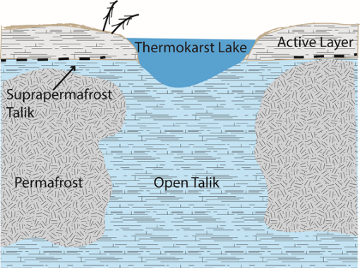
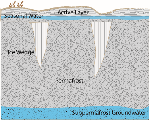
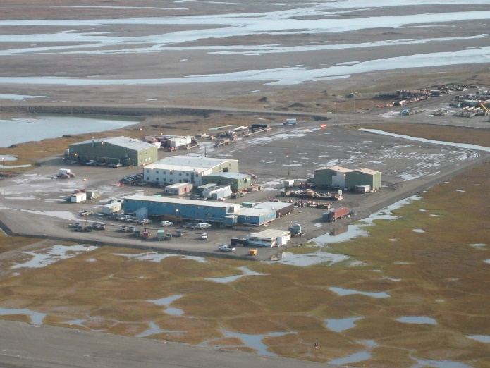
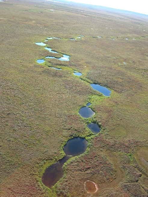
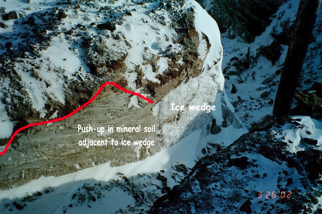
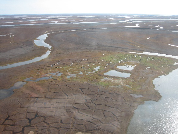
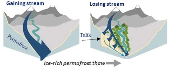
7.12.3 Assessing Vulnerability
The vulnerability of remediation sites to permafrost thaw should be assessed. See Sections 6.1.3 and 6.1.4.1 for an overview of how to conduct an exposure assessment, and Sections 6.2.3 and 6.2.5.1 for an overview of when and how to conduct a vulnerability assessment. In addition to reviewing weather records and forecasts, trends can be evaluated.
- Identify the permafrost characteristics and thaw stability of the soil across the entire footprint of planned or existing infrastructure and known contaminant location (Schnabel, Goering, and Dotson 2020).
- Use online resources for digital elevation models and permafrost predictive maps.
- Elevation data can be found at Alaska’s Division of Geological & Geophysical Surveys or the University of Minnesota’s Polar Geospatial Center.
- The University of Alaska Fairbanks Geophysical Institute Permafrost Laboratory maintains a near real-time data set and interactive online graphs available to the public of temperatures (both air/surface and borehole), soil pit temperature and water content, and snow depth for various locations across Alaska, along with links to many other resources and maps.
- Temperature and precipitation projections, frequency of extreme temperature, and permafrost risks and hazards are accessible as GIS data sets through the Alaska Climate Adaptation Science Center.
- The Denali Commission has identified communities at risk from thawing permafrost in Alaska, published in the Statewide Threat Assessment (University of Alaska Fairbanks Institute of Northern Engineering 2019).
- By 2023, the Permafrost Discovery Gateway will provide a browser-based platform for visualizing and exploring data in Arctic regions—from the historical and predictive modeling perspectives down to the submeter scale (Schnabel, Goering, and Dotson 2020).
- Sites vulnerable to permafrost thaw may also be vulnerable to storm surge (Section 7.11), evapotranspiration (Section 7.10), bank and shoreline erosion (Section 7.6), flooding (Section 7.5), fluctuating groundwater elevation levels (Section 7.4), sea-level rise (Section 7.9), wind (Section 7.2), or wildfires (Sections 7.7 and 7.8). Review of the SBMPs for those events is encouraged.
- If the cleanup site is near but not overlying permafrost, evaluate vulnerability to secondary impacts from permafrost thaw (Section 7.12.2.5).
7.12.4 Planning and Prioritizing Resilience and Sustainability
- Assume the permafrost at the site will thaw over time and design the remedy and any infrastructure with flexibility to withstand destabilizing ground conditions or adapt the existing design.
7.12.4.1 Site Characterization
- Characterize the tundra terrain. Walker (1983) is a well-regarded reference for tundra characterization.
- Characterize the boreal forest type.
- Characterize the presence, abundance, type, and location of subsurface ice (Jorgenson et al. 2015). Use remote sensing methods, such as Lidar, or historical data as much as possible to avoid physically disturbing the terrain.
- Use geophysical surveys over the entire footprint of the remedial site at the beginning of the investigation to identify optimal locations for investigative boreholes to minimize destructive activity in the tundra (Schnabel, Goering, and Dotson 2020). Ground penetrating radar is a common method for identifying the top of the permafrost layer.
- Use electrical resistivity to identify subsurface ice bodies and characterize the physical state of interstitial water (Schnabel, Goering, and Dotson 2020). Electrical resistivity surveys can show the health of permafrost and in particular, taliks in the subsurface or salty liquids in permafrost. Direct current electrical resistivity tomography (ERT) is recommended for a shallow survey. When deeper information is required, the very low frequency electromagnetic tools are very useful.
- Consider conducting fly-over electromagnetic surveys by helicopter for large-scale cleanups or infrastructure planning (Daanen et al. 2016, USGS 2011).
- Characterize the local groundwater flow using stable isotope tracers with a monitoring well network.
- Decommission boreholes in a manner that preserves the thermal regime.
- Sample nearby surface water for the contaminants of concern to determine if supra-groundwater flow to the water body has occurred. This is important even if the water body is not downgradient from the source or in alignment regional hydrology.
7.12.4.2 CSMs
- Evaluate which landscape-scale changes are anticipated in the vicinity of and over the design life of the infrastructure component (Schnabel, Goering, and Dotson 2020).
- Include the likelihood for thermokarst development, subsidence, and thermal erosion at the site.
- Consider that subsidence may modify topography and hydrology and change the surface-water drainage patterns for the site.
- Include drying surface soil and vegetation in the evaluation of contaminant availability and migration.
- Consider how contaminant migration might be affected by permafrost thaw and secondary impacts (Section 7.12.2.5).
- Weigh the risks of contaminant migration after thaw against the risks of destroying tundra and creating additional thaw.
- If contamination is on the coast, determine if the coastline is subject to sea-level rise (Section 7.9) or increased erosion (Section 7.6) and whether more aggressive remediation of the contaminant is warranted prior to failure of the coastline and release into the open ocean.
- Evaluate in situ treatment techniques to eliminate the ongoing need for containment.
- Evaluate how the landscape is expected to change (for example, from dry to wet) and consider how the expected changes over time may impact exposure pathways and mitigation measures, whether planned or already installed.
- Consider the soil and groundwater temperature and whether they are likely to increase over time, affecting the contaminant cleanup levels. Use the Alaska Climate Adaptation Science Center Climate and Weather Tools.
- Consider that methane may become an additional contaminant of concern at the site, and/or create additional site hazards if released from permafrost as it thaws.
7.12.5 Remedy Design and Implementation
- To the extent practical and allowed by regulating entities, complete all work in the winter.
- Minimize surface disturbances, including compaction and the footprint of any construction.
- Retain the active layer and vegetation where possible to serve as insulation for the underlying permafrost.
- Locate structures in areas of the site least sensitive to thermokarst—for example, on coarse-grained soil, such as gravels free of ice wedges, which will have minimal settlement and maintain foundation strength when the pore ice melts. Dry tundra or fine-grained soil will also generally have minimal settlement (USACE CRREL Permafrost Tunnel Research Facility, see Permafrost Thaw-Stability section).
- Minimize soil compaction to avoid affecting site drainage pattern and thermal changes. The following protective measures are from Cater (2010):
- Limit foot and vehicle travel on all tundra types as much as possible, especially in the same area, by using a different pathway to enter and exit the site.
- Use snow ramps to access tundra from gravel roads and pads.
- Use existing infrastructure and roads whenever possible.
- When existing infrastructure is not available:
- For high foot-traffic areas plan to use boardwalks light enough to be moved manually, so they can be easily moved around the site as needed, and removed at project completion.
- Use snowshoes when repeated trips on foot cannot be avoided.
- For light equipment consider using compressed snow or ice pads or other working platforms as appropriate.
- For heavy equipment consider using appropriately designed ice pads and/or interconnected rig mats as appropriate.
- Follow the guidelines provided by ADNR for tundra travel and obtain a permit for construction of snow ramps, ice roads, and ice pads, and for any vehicle traveling on tundra on state-owned land on the North Slope during any season. Visit the ADNR Tundra Travel website to view current tundra conditions, sign up to receive email notifications about travel in the tundra, and find appropriate contacts to obtain off-road travel permits.
- Do not use vehicles to cross ponds, lakes, or the wetlands immediately bordering these areas. Avoid crossing areas where more than 3 inches of standing water are present.
- Avoid making minimum-radius turns with sharp articulations with vehicles.
- Develop an infrastructure rehabilitation cycle of 15 years maximum and incorporate climate adaptation into it.
- Install barriers to replace permafrost where contaminants are water-soluble to prevent subsurface migration.
- For surficial spills where permafrost has thawed, evaluate whether cleanup methods other than flooding and flushing are appropriate (Lukin et al. 1999). If flooding or flushing are used, consider using naturally occurring surface waters pumped from strategic points to the spill, and/or cool the water to 0ºC.
- Design for cleanup levels appropriate for soil and groundwater with warmer temperatures. Identify the infrastructure thermal processes and minimize or insulate them to the extent practicable.
- Identify if any trails through the tundra exist on the site, which may be used by wildlife or for harvest activities (SEARCH 2018).
- Locate infrastructure or equipment away from trails.
- Consider incorporating trail hardening and stabilization into the site design to add a social benefit (Section 5.9) to the cleanup.
- Use thermal modeling software to understand heat transfer in Arctic soil beneath planned infrastructure. There are models capable of simulating the progression of permafrost thaw that may occur as a response to either climate change or the placement of warm infrastructure (Schnabel, Goering, and Dotson 2020).
- Heated buildings, warm pipelines, or other warm structures should be separated from ice-rich permafrost to avoid inducing thawing (Schnabel, Goering, and Dotson 2020). Separate them from the ground surface by
- placing them on a foundation with pilings that are frozen into the permafrost
- creating a ventilated space under the structure
- placing them on a thermal pile with passive cooling systems such as thermosiphons or an active cooling system such as a heat pump or solar energy. [Note: Be aware that pilings and thermosiphons are less effective where permafrost temperatures are warmer (Schnabel, Goering, and Dotson 2020). One advantage to thermal pilings is that they can be adjusted as the ground surface elevation changes over time from subsidence or heave (SEARCH 2018).
- If constructing the building on grade, install insulation and a cooling system (for example, mechanical refrigeration, ventilation ducts, thermosiphon cooling system) below the building footprint.
- Design linear structures, like a road, with an embankment height that ensures that the annual summer thaw will not penetrate the permafrost (Schnabel, Goering, and Dotson 2020).
- Remove or pack snow to help release heat from the ground or conduct cold into the ground, respectively, and stabilize the permafrost prior to construction.
- Use insulated Arctic pipe or heavily insulated utility corridors above the ground surface to protect permafrost from any warm flowing liquid in pipes.
- Install sensors to monitor the extent of changing pressures and stresses on structures or to monitor subsurface geophysical conditions relevant to infrastructure performance and failure (DOD 2019, NOAA 2016).
- Locate infrastructure and key equipment away from any potential path for a slow-moving frozen debris landslide.
- Consider permafrost with high ice content as thaw-unstable with the likelihood to cause structural failure for anything built on top of it (Schnabel, Goering, and Dotson 2020). Evaluate alternatives to trenching to limit the lateral extent of flow. Trenching may have drawbacks of disrupting the thermal regime and may cause thermokarst (Cater 2010). Trenching may also lead to further disturbances and contaminant migration if the trench intercepts a natural stream, river, or swale (Cater 2010).
- Do not use equipment larger than necessary.
- Remove soil only to the depth to which contaminants have infiltrated.
- Where excavation is required in locations with ground ice, or suspected of containing ground ice, over-excavate to ensure the thaw depth does not exceed the lower boundary of the backfilled soils (Barnes 2015). This depth changes dramatically when the vegetation and organic layer are removed. We recommend using thermal modeling to find the appropriate depth of backfill.
- Complete excavations and backfilling before the active layer thaws (Barnes and Biggar 2008).
- Backfill excavations with material of similar particle size and relative amounts of organic matter, gravel, sand, and silt to the surrounding area (Barnes 2015, Cater 2010).
- If large enough quantities of native fill are not available for backfilling, at a minimum place 1.6 feet of native fill on top of the fill material to finish bringing the excavation to grade. If native or local organic soils are not available, import nonnative peat soil in compressed bales for this purpose.
- Place organic material on top of mineral soil for the maximum effect on the thermal regime.
- Use cold soils and allow the backfill to freeze completely. Ensure cooling by removing snow cover if it accumulates after completion.
- Replace displaced tundra sod back into original divot, or transplant tundra sod to replace soil and vegetation that have been removed. Traditional ecological knowledge (TEK) for sodding techniques based on techniques for roofs and ice cellars may be applicable (Cater 2010).
- Maintain existing natural contours and surface-water flow patterns.
- Consider the microclimate of the area you are revegetating and choose appropriate native plants and/or local seed sources.
7.12.6 OM&M
- Continue monitoring site soil temperature, soil moisture content, ice, and hydrologic conditions, including periodic sampling of nearby surface waters for contaminants of concern.
- Continue monitoring groundwater for changes in temperature, flow direction, or contaminant distribution.
- Consider monitoring for methane as a new contaminant of concern if permafrost thaw progresses or subsurface conditions warm.
- Evaluate landscape changes periodically. Containment strategies and/or cleanup levels may need to be revisited and/or refined over time due to landscape changes.
- Monitor infrastructure for frost heaving and/or subsidence.
- Implement the infrastructure rehabilitation cycle every 15 years at the most.
- Monitor sensors to identify the extent of changing pressures and stresses on structures or subsurface geophysical conditions relevant to infrastructure performance and failure and conduct rehabilitation when a threshold is reached (DOD 2019, NOAA 2016).
- Minimize surface disturbances, including compaction, and retain the active layer and vegetation where possible to serve as insulation for the underlying permafrost.

